again using a fly-back transformer
My Cockroft-Walton-Multiplier (cascade)
again using a fly-back
transformer ![]()
Table of contents:

Circuit plan (only some of the 22 stages drawn
):

An additional cap has to be inserted when joining the lower and upper 150kV cascade. Since I want to change the polarity by turning the stack upside down, I'll house the cap in a way that it can be "clicked-in". On the lower end, a shorting bar has to be inserted:

I plan to start with a 150kV-stack and make a second one which can be added
on top of the first one - the CW multiplier doesn't multiply, it adds the
voltages... I also want to have the flexibility in polarity, so I'll try
to buildt it in a way that I can flip the HV-stack upside down to reverse
polarity. Finally having two 150kV-stacks, I can make one positive and the
other negative polarity (need two Rout units then!) or stack them for 300kV
of either polarity:

Calculation of the height of the construction:

The 5cm at the lower and upper end is due to the stackable approach. The
tube connector of the brown 75mm diameter center tube is 12cm, the overlap
4.3cm and 4.8cm (middle section 3cm).
Cross section will be something like this:

The potential rings have to be wider as the routing of the wire between the
components (mainly due to wire in white PVC tubes between caps). So far I
think I need at least 3.5cm clearence from the components/wires to the potential
ring, the inner diameter of the potential ring has to be at least 18cm!
I'll arrange the components (red: capacitor, blue: resistor, black: diode) around a beautiful shiny brown 75mm diameter tube (looks like the brown line isolaters for >>10kV), add some fiberglass plates (yellow) to increase stablity and provide a rigid frame to connect the potential rings (grey) to. The screwed connectors between the fiberglass boards are black PVC tube with screwes at the ends. The orange ring in the schematic above is a bigger tube in which the CW will be stored. It will be removed before going alive on stage of course.
Each 150kV-stack will have a height of 0.60m without toroids when build like depicted above.
At first, I tried to arrange the caps vertically, the caps have a length of 48mm and will be spaced 7mm apart to allow soldering. But that resulted in 55mm per stage. Currently, I make a redesign and try to place the caps more horizontally, so that the height can be decreased. Of course the whole thing gets wider then. But considering the final version with 300kV and 3 toroids, the whole thing else will be ~2.1m tall with the caps standing upright (ooops, I planned 1.5m)! The horizontally arrangement will allow for 43mm height per stage if I place some tubing arount the wires between the caps to prevent arcing (hopefully, not ested up to now...).
Another limiting factor besides diameter (storage!) and height when fully erected (for firing) is the size of the styrofoam rings I plan to use as potential rings. I only can get them in 200x40mm, 220x40mm, 250x50mm and 300x60mm at the moment. Perhaps I'll use selfmade rings of installation tubing (for house wiring) which I have in 25mm outer diameter and which I can get eventually in approx. 40mm outer diameter.
I'll build a small modell with only 4 stages at first to get some experience. I don't know how tricky the air insulation is in reality and I don't want to drill any holes in the wrong place all over the big structure.
Simulation of small model with 4 stages:
Since I'll build a small modell with only 4 stages at first, I tried to simulate it's behaviour. With the student version I only can do a simulation with up to 7 stages, so I can't simulate the whole model anyway.
The simulation was done with 50k and 63k resistores
at the diodes, which I planned to use originally. BEcause of their insufficient
voltage rating, I aquired some 100k resistors. A first calcuation showed
nearly identical results, therefore I leave the old simulation results
here:

Rload is shown as 1Ohm, that's short circuited. Other values for simulation
are 50.000kOhm and open (10GOhm).
Since I didn't measure the short circuit current my driver can deliver up to now, I "guestimated" its impedance from the input power and output voltage. The frequency (also not measured under load until now) is set to 15kHz, the voltage 13.5V, that's 1/500 of the measured actual voltage. Therefore all the voltages and currents in the simulation results have to be multiplied by a factor of 500!
The following simulation shows the open circuit voltage of 47.5kV:

and here zoomed to the according input current (25mA at the beginning, dropping
down to 9mA after 90ms, output currrent remains zero since this is open
circuit):

The next image shows the simulation with Rout=50MOhm. The output voltage
is still 26.5kV:

With Rout=50MOhm, input current starts at 25mA and drops down to 11mA after
~180ms:

while the output current through Rout=50MOhm rises to 0.55mA:

Those 0.55mA at 26.5kV in the output resistor is 15W output power at 50MOhm
load.
Finally a simulation with a short at the output. The input current is 24mA
and the output current 12mA amplitude AC with an offset of approx. -3mA:

Here are the first images of the 4-stage test-CW:
That's the prototype of the potential ring:

After tightening the two turns of heavy wire inside the tube (over a mandrel
of 18cm diameter), I wrapped the joint with clear Tesa tape because it has
more strength than the electrical tape. Then a layer of electrical tape is
applied. After that, a lot of thin small stripes of alumnium tape (DIY store,
plumbers section) are applied. finally, all the wrinkles are smoothed out
with the help of a spoon (rub it over and over). Now the ring has much more
strength/stability and stays in form when bent to a flat (!) and really circular
ring (at the beginning it will look like a wobbly egg). I'll
place some more images on that topic here soon...
![]()
Here is the brown tube connector, looks like the brown ceramic of commercial
HV line insulators:

And that's the 4-stage CW in it's current state:


The curled green wires at the top (and bottom, but on the backside) of the
tube just "simulates" a spark gap - it reminds me to put some acorn nuts
on a threaded rod when the fiberboard is in place. The blue ones are the
resistors which will limit the current through the (black) diodes when the
cascade is discharged. The white tubes between the caps contains just the
wiring because the caps are not insulated very well. Hopefully this will
prevent discharges between the components. This it the gap before
installation:

Oh, and yes, I know, I should put some bleeder resistors across the caps. But it's really hard to find some cheap resistors rated for approx. 6GOhm and 30kV (need 44 pieces of them). Perhaps I'll build a nice earthing system like Haefely uses on their SGDA-Marx-generators (see page 11 of http://www.haefely.com/dropbox/cms/files/SGDA_low_resolution.pdf). A first schematic how this will be wire is shown above.
Width of the fiberboard is 15cm, spark gaps are in a distance of 3cm to the
outer edge of the outermost cap, connections between fiberboard 2cm from
spark gap (2cm from outer edge of fiberboard):


I bought two "flat" 30x6cm styrofoam toroids. Flat means that I have to combine
two halves. Actually, the "halves" are a bit thicker, so total thickness
is 8.5cm instead of 6cm. This should be a suitable toroid (actually way
oversized) for the top of my 50kV-cascade (4-stage test setup):


I got some cheap (empty ;-)) film containers with 18cm diameter. I'll use them (well, only the upper parts which are not as thick as the bottom parts) as top plate and bottom plate of the stack as well as the plate of the top toroid.
For the first light, I choose the ignition circuit
as the HVAC-source, it deliveres approx. 6.5kV (open circuit, not connected
to the CW-multiplier). Testing of the ignition circuit was done with two
TV cascades without a suitable cap in the feedline (usually omitted in the
commercial TV cascades). Old blue TV-cascade delivered 29.4kV without cap
in the feedline, green new TV-cascade delivered 31kV without cap in the feedline.
I tried a 0.8nF cap and a 4.7nF cap in the feedline of
both cascades, but output decreased significantly. The measurements have
to be performed again with a better setup of the peak rectifier.
![]()
Since we saw that there was a significant output (lots of hissing), we decided
to do the first light of the 4-stage test setup with this ignition circuit
as a the source (voltage is perfect for the 30kV rating of the caps in the
cascade). We started with negative polarity this evening. Since this was
only a test setup, I did not connect the potential rings to the smoothing
column. In fact, I just slided them over the acrylic plates without any
fastening, therefore the whole thing looks like it was found in the
dumpster...:

Below the multiplier stack I placed some cardboard boxes to prevent arcing
through the carpet to the screed (wife would be not amused if I would melt
some holes in it...). I was not sure if the output resistors would withstand
the surges, I just taped them to an insulaing rod placed inside the middle
tube of the arrangement.
Each stage delivered approx. 12kVDC. With the corona rings in place but not connected to the caps, corona decreased the output of the upper stages a bit. Output of second stage was 24.3kV, of the third stage 34.7kV. Since the high voltage probe is only rated 40kVDC and I had no other suitable equipment at hand at this time, I did not measure the output at the 4th stage (guess is 43kV with all the corona around).
Last time we buildt our lifters, they won't fly (DC flyback as the source).
Now we tried them both with the 4-stage CW. Please click the images to see
the movies:


The flights were very unstable, but with the experience of the mini lifter
I was prepared. Therefore I added three 68kOhm resistors to limit output
current in case of a short between the wires.
After the successful flight, we wanted to have more fun. A ball of alumnium
foil (3.5cm diameter) was placed on top of the 4-stage test cascade and we
used a plastic wand with a grounded brass ball (1cm diameter) to draw some
impressive fat arcs of 5cm (2") length. Click the image of the screenshots
to see the 15s video clip of the arcs:

As the simulations above indicate, the cascade needs approx. 0.5s for recharging, the spark repetition rate was approx. 2Hz when the grounded wand was held in constant distance.
2nd light: I managed to draw 7cm arcs with a bigger topload (the 4 potential rings stacked on top)! Repetition rate is much higher (5-10Hz). The feeding resistors (4pc. 100kOhm in parallel) get warm. I guess max. 3W of heat. That would work out to I=SQR(P/R) = SQR(3/100k) = 5mA. If we assume a drive voltage of 5kV (it will drop under load), that's 25W when arcs are drawn repeatedly (mmh, its hard to count the arcs per second, anyone an idea to do this automatically?). Values to be verified with the help of some better instruments than just my fingers. See below for the real values!
3rd light: I managed to destroy one of the 100kOhm resistors rated for 10kV. It was the top one of the upper stage and happened when I draw arcs with reduced Rout (used only 2 and then only 1 of the 63kOhm resistors). Seems as if I have to readjust the protection spark gaps.... Because of this, I'll use all the 63kOhm resistors I own as the Rout (total of 945kOhm).
Another issue to think over is the feeding resistor. I paralleled four resistors each 100kOhm (rated 10kV) for a total of 25kOhm. If we assume an input power of 100W (far in the future...) at 6kV, current will be no more than 17mA. Lets calculate with a peak value of 10 times that. The voltage drop across the 25kOhm resistor will be U=R*I=25kOhm*170mA=4.2kV. So it still is a good idea to use the resistors with the 10kV rating. Dropping the resistance will increase the possible current, therefore the voltage drop will remain nearly the same.
First measurements (still without potential rings):
a) multiplier w/o load:
With 230V into the ignition circuit and the 1GOhm
high voltage probe (rated 40kVDC) at the output of the CW-multiplier, I got
41kV output. Input current (using the 25kOhm feeding resistor) was 2.7mA
with no load (besides the probe), the input voltage was 5.85kV peak. That
works out to 16VA input power at no load (just the probe). Efficiency of
the 4-stage multiplier is 41kV/(2*4*5.85kV) =
41kV/46.8kV = 88% at this load condition. Lets calculate
how severe the load presented by the high voltage probe really is:
1GOhm at 41kV is 41uA output current of the multiplier, or 0.33mA input current
into the multiplier (Iin=2*n*Iout), that's 12% of the
total input current. Will be interesting to see how this
changes with the 6GOhm probe I'm going to build soon. (Rough estimation:
if all the input current will be used for increasing the voltage instead
of delivering output current, the output voltage would rise to
2,7mA/(2,7mA-0,33mA)*41kV = 1.14*41kV = 46.7kV, the efficiency would be 99.8%,
that means there are no other significant losses in this no-load
condition.)
b) multiplier short circuited
![]() More
measurements to come...
More
measurements to come...
c) repeated arcs
![]() More measurements
to come...
More measurements
to come...
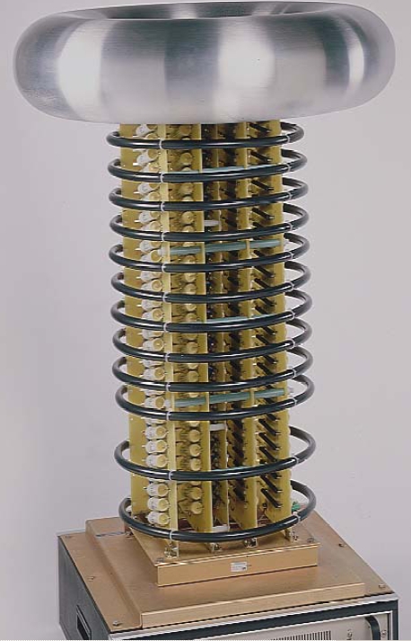
Again some photographs of the latest progress (compare to the original at
the right!):


Now it looks much better compared to the "first light setup" ;-) As in the
original, the driver circuit will be located in the base (here an alumnium
case).
Here is the wiring scheme for the case:

I now have finished the case and the output resistor stack. Everything can
be screwed together:
 (red cable from top toroid
is for grounding when not in use)
(red cable from top toroid
is for grounding when not in use)
![]() More detailled images will
follow, stay tuned....
More detailled images will
follow, stay tuned....
First test with different polarity showed that positively charged top toroid led to only half the discharge length than negativly charged top toroid (earthed electrode was 1cm diameter brass ball in both experiments). More to come...
![]()
Since the diodes are rated 18kV and the caps 30kV, I can drive the current setup with max. 18kV per stage (should be below 15kV to have some safety margin). I plan to add a second diode everywhere in series to be able to use up to 25kV per stage (that's 66% more!). So I still have 5kV safety margin on the caps...
![]()
My analog HF current meter showed me approx. 6mA input current into the cascades
HV stack (ignition circuit as the driver), still have to perform a complete
measurement of all parameters at the same condition...
Another measurement at the GTL-Teslathon2006 resulted in 42.4kV output voltage
(open circuit).

The image above shows from left to right: the flying styro flake, the spark
table (showing "GTL" when energized, see image and videoclip below), earthing
stick (yellow/red), connector rod (black), 40kVDC peak voltmeter (VOM with
red HV-probe and brown cap tube with white rectifier rod on top), analog
HF current meter (black box in foreground), 3.3nF@40kV pulse cap (brown tube
with ball on top) suitable for direct shorting (to increase the SNAP and
brightness of the discharge from the CW-multiplier), CW-multplier, isolated
stand.


 click
it to see the movie!
click
it to see the movie!


 |
Here is a short video clip of the
spark table (without additional spark gap and without pulse cap ) in action at the GTL-Teslathon2006 (right click it to download and watch it multiple times with your favourite video player). |
 |
This second short video clip shows increased performance of the spark table with the pulse cap and additional spark gap. |

![]()
![]()