Exploding wires, can crushers, coin shrinkers, ball lightning
High energy page
![]()
Exploding wires, can crushers, coin shrinkers, ball lightning
WARNING: big caps (>50J) are absolutely
deadly!
Defibrillators have approx. 500J, we are dealing
with energies an order of two magnitudes higher (up to 50kJ)
here!
50kJ equals dropping a VW Golf (a german car with 1400kg) from 3.5m, better
not to stand under the weight!
![]()
![]()
|
||||||||
A short summary on the things you can do with high energy (pulse) caps:
| ring launcher (disk shooter) |
exploding wire | coin shrinker | can crusher | |
| 0.5kJ | 5 1/4" HDD, flight height some meters | some 10cm wire (0.4mm dia) |
- | crumple a can |
| 1kJ | 5 1/4" HDD, flight height some ten meters | - | crumple a can, will be ripped apart when scratched before | |
| 2kJ | >6" of wire (0.5mm dia) |
shrunk to 87% diameter | can ripped apart | |
| 5kJ | shrunk to 73% diameter |
I'll start small with electrolytic caps (slower discharge) and will perform some exploding wire experiments as well as performing "ball lightning" experiments. After that I'll move to the big array of MP-caps and do some coin shrinking experiments.
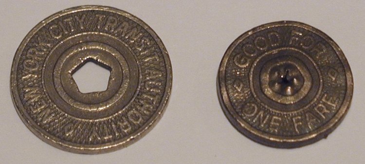
This New York City Transit Token was shrunk by Bert Hickman
(http://www.teslamania.com). I bought
it from him together with a beautiful Lichtenberg figure (I placed a
photograph of it on my lightning page). Bert provided
the following data about the shrinking process:
"The Quarter Shrinker uses a capacitor bank consisting of two 70 uF caps
connected in parallel, so the current bank size is 140uF at
12kV. The NYC subway token that you received was shrunk using
a coil made from ten turns of #11AWG
(4mm2)"heavy" build (double thickness) 200°C
magnet wire. The capacitor bank voltage was 9600V, representing
about 6.45kJ of potential energy.
During the shrinking process, the estimated peak work coil current was
~82kA, and the token shrank to its present size by the time
the first current peak was reached (~26us). The estimated peak
magnetic field within the work coil was ~410 kilogauss
(~41T), and the maximum rate of change in work coil current
was ~5e9A/s. Before it exploded, the coil "felt" an internal
magnetic pressure of approximately 50tons/square inch (similar
to the pressure of a confined gas), and the coil fragments ejected by the
exploding work coil are believed to attain velocities of
1000-1600m/s.
Needless to say, coin shrinking is a very energetic process... :^) "
From the time to the first peak (26us), the frequency can be calculated to f=19.2kHz.
The energy preservation 1/2*LI2=1/2*CU2 (without damping) gives a value for L of => L=1.9uH, but Thomson's formula f=1/(2Pi*SQR(LC)) without damping results in L=0.49uH. So most probably, L is in the range of 1uH.
Simulating this event with microsim, the spark gap resistance must have been in the range of below 0.05 Ohms (my original guess for such spark gaps was 0.2-0.5 Ohms) to achieve such a high current (would have been only 43kA for 0.2 Ohms or 22kA for 0.5 Ohms). So the performance of the spark gap definately has a BIG influence on the peak current.
Here are two rough simulations of the parameters I've done with the help
of the RLC simulator at
http://www.coilgun.info/mark2/rlcsim.htm:

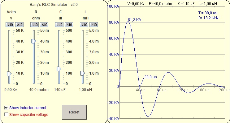
Not a perfect match but close. So the spark gap resistance definately
seems to be in the area of 20mOhms.
![]()
As long as I have not performed my own experiments, I'll post here some data of the results other people have achieved:
Disc shooter:
| who | capacitance | voltage | energy | projectile | flight height | coil | voltage leftover | URL |
| Tristan Stewart | 8uF | 10kV | 400J | Copper ring (gasket), very thin |
50 feet (!!!) | #8 AWG standard THHN copper wire wound around 4" PVC, in a close-wound selenoid of approximately 40 turns | ? | http://members.tripod.com/ ~mad_coiler/ringlauncher/ |
| Tristan Stewart | 120uF | 7kV | 3kJ | 51/4" MFM-HDD |
Approximately 125' | 15 turns of #12 wire, flat spiral | ? | http://members.tripod.com/ ~mad_coiler/ringlauncher/ |
| Tristan Stewart | 120uF | 5kV | 1.5kJ | 2"x4" (20- 30cm long) placed on an 51/4" MFM-HDD |
"We quickly found out that we had to run after firing the coil...as a 2x4 came falling from about 75' up in the air!" | 7 turns of #8 wire (???) | ? | http://members.tripod.com/ ~mad_coiler/ringlauncher/ |
| SB | 800uF | 1320V | 700J | 5 1/4" HDD | flight height 1-5m | ? | ||
| Sam Barros | 3kJ | http://www.powerlabs.org/capexperiments.htm |
exploding 'wires':
| who | capacitance | voltage | energy | diameter / thickness | length | voltage leftover |
URL |
| MD | 1650uF | 700V | 404J | 0.3-0.4mm (!!!) | 50cm | 200V | |
| Fleischwulf | 32uF | 6125V | 600J | #24 = 0.5mm (!!!) | 4"=10cm | ? | 25000J(!) Maxwell-cap (32uF, 40kVDC, 90kA) |
| SB | 800uF | 1320V | 700J | 0.4mm | "some length" | 100V | |
| SB | 800uF | 1320V | 700J | - | strip of aluminium foil | http://home.t-online.de/home/ 0947197197-0001/new.htm |
|
| SB | 800uF | 1320V | 700J | - | salt water | http://home.t-online.de/home/ 0947197197-0001/new.htm |
|
| SB | 800uF | 1320V | 700J | - | strip of the metal of a coke can | http://home.t-online.de/home/ 0947197197-0001/new.htm |
|
| Tristan Stewart | 120uF | >5kV nötig | 1500J | #24 AWG bare copper wire |
6" long section | http://members.tripod.com/ ~mad_coiler/expload/ |
|
| Greg Leyh | taser cannon, 15kA | 110kV | 0.008" = 0.2mm | 35 feet (!!!) | http://www.lod.org/otherdevices.html | ||
| Greg Leyh | super taser (planned) | 250kJ | 50 feet | http://www.lod.org/otherdevices.html | |||
| Herwig Roscher | 30µF pulse caps | 10 kV | 1.5kJ | 1,5mm^2 | 1m Cu wire |
can crushers: (hard on the caps due to many voltage reversals in the long ringing!)
| who | capacitance | voltage | energy | effect (can diameter) | coil | voltage leftover | URL |
| Tristan Stewart | 120uF | 3kV (-5kV) | 540J (-1500J) | even at only 540J the can was really crumpled (!!!) | 5 turns of #12 wire |
http://members.tripod.com/ ~mad_coiler/cancrusher/ |
|
| Tristan Stewart | 120uF | 6000 | 2160J | can ripped apart | 5 turns of #12 wire |
http://members.tripod.com/ ~mad_coiler/cancrusher/ |
|
| SB | ? | ? | 600J | doesn't work (perhaps because too low voltage) |
? | ||
| Fleischwulf | 32uF | 8kV | 1000J | ok | ? | ||
| Uni Köln (according to JR) |
320uF | 3-3.5kV | 1440-1960J | approx. 2cm, ripped apart when scratched before |
? | ||
| somewhere in the web accoring to CGB |
400uF | 3kV | 1800J | ok | ? | ||
| JR | 60uF | 9-10kV | 2430-3000 | 2cm, ripped apart when scratched before | ? | ||
| Erich Hans (can crusher, coin imprinting,...). 40kV-contactor |
300uF | 3.5kV | 1.8kJ | http://www-nw.uni-regensburg.de/ ~.hae18166.allgemein.physik. uni-regensburg.de/Crusher.htm has more caps => 3.3kJ at 3.5kV (540uF) charging current 2mA (6kV/2mA-power supply) means approx. 20s/100V => ~12 minutes charging time!!! |
Here are some links to images, description and high speed video of a can
crusher in action:
http://www.physics.umd.edu/lecdem/services/demos/demosk2/k2-62.htm
http://www.wesleyan.edu/physics/demos/e&m/2khzvsmall.mov
(see the parts of the can flaying away in opposite directions)
http://hibp.ecse.rpi.edu/Can_Crusher/home.html
http://hibp.ecse.rpi.edu/Can_Crusher/photos.html
(look how fat the arc is between the electrodes of the spark gap!)
Coin shrinker:
| who | capacitance | voltage | energy | effect (diameter of the Quarter) | coil | voltage leftover |
| Video from Achim | ? | 27kV (1-40kV) | ? | approx. 50% | various, best is (at 27kV) ~8-10 turns | ? |
| Fleischwulf | 32uF | 25kV | 10kJ | 50% (noticable effect above 1kJ) | ? | |
| Bert Hickman: http://www.teslamania.com | 1.6kJ 2kJ 2.5kJ 5kJ ... -21kJ |
91% dia 87% dia 82% dia 73% dia ... "quarter-ball" |
||||
| Ross Overstreet | 178uF | 9kV | 7.2kJ | 90%? | 10 turn 10ga | |
| Erich Hans:
coin imprinting |
300uF | 3,5kV | 1,8kJ | http://www-nw.uni-regensburg.de/ ~.hae18166.allgemein.physik. uni-regensburg.de/Crusher.htm has more caps => 3.3kJ at 3.5kV (540uF) charging current 2mA (6kV/2mA-power supply) means approx. 20s/100V => ~12 minutes charging time!!! |
MD> Und so konnte ich ein "exploding wire"-Experiment im Unterricht vorfuehren. Die caps waren in Serie geschaltet fuer 1650 uF bei 700 V. Der Draht: ein duenner Kupferdraht. Ein riesiger, alter Messerkontakt-Schalter diente als Schaltelement. Wow ! Es hat wirklich laut geknallt ! War wirklich toll !
STK>Das sind also 400J bei 700V (1650uF). Weisst Du noch, wie dick Dein Draht war, Martin?
MD> der Draht, der bei meiner Vorfuehrung so schnell "annihiliert" wurde, muss etwa 0.3-0.4 mm im Durchmesser und etwa 50 cm lang gewesen sein. Ich kann es leider nur schaetzen, das Ganze ist schon sechs Jahre und ich hab dazu keine Notizen gemacht. Bemerkenswert war jedoch die Tatsache, dass sich die caps bei der Pulsentladung keineswegs vollstaendig entluden. Danach waren doch noch etwa 200 Volt drauf (nicht ungefaehrlich, diese "Restladung" !).
SB> Ich habe ähnliche Erfahrungen gemacht (wie MD). Früher
hatte ich alle meine Fotokondensatoren parallel, da brannte der Draht meistens
nur durch, und es blieb auch eine ziemlich hohe Restspannung übrig.
Als ich sie dann auf 660 bzw. 1320 Volt (700Ws Kondensatorbank mit
Fotoblitzkondensatoren) umkonfiguriert habe, konnte ich längere Drähte
vollständig verdampfen. Die Restspannung bleibt jetzt meistens unter
100V. Mein Kupferdraht hat übrigens einen Durchmesser von 0,4mm.
Meine Theorie: je hoeher die Spannung, umso leichter tut man sich beim exploding
wire, denn der Strom muesste meines Erachtens dann groesser sein. Oder irre
ich mich hier und man sollte lieber eine groessere Kapazitaet mit niedriger
Spannung daraus machen????
MD> Deiner Theorie bezueglich hoehere Spannung bei gleichviel Joule kann ich nur unterstuetzen. All die brutalen caps, welche z.B. zum magnetoforming (Umformung von Werkstoffen durch extrem strarke Magnetfelder) arbeiten mit Spannung zwischen 20...30 kV. Ein weiterer Vorteil von so hoher Spannung ist das einfache Schalten. Man braucht sich bloss eine solide Funkenstrecke zu bauen. Dann stellt man die gap so ein, dass sie dann zuendet wenn der cap seine volle Ladespannung erreicht hat. Solche gaps sind auch ziemlich effizient, sie sind die verbreitetste Form von Schaltelement in der HV-Technik.
MD> Mein Gott, ich krieg schon wieder Lust was mit meinem Maxwell
14 uF/25kV-Pulscap zu machen. So ein can-crusher waere schon was tolles...
JR> vor zwei Wochen habe ich einen can-crusher gebaut: 12 MP-Kondensatoren
80uF, 3kV von denen jeweils 4 in Serie und drei parallel geschaltet sind.
Die resultierenden 60uF werden auf 9-10kV geladen und über eine
Druckluftfunkenstrecke (Druckablaß=Zündung) an eine Spule aus
6mm Cu-Rohr mit 5 Windungen geschaltet (Windungsabstand ca. 5mm). Die Spule
ist zur Isolation in Zweikomponenten-Kautschuk eingegossen. Kunststoff aus
dem Baumarkt zur Befestigung von Glasfasermatten am Auto eignet sich nicht,
weil er stark schrumpft und reißt.
Alu-Dosen (Wasser, Red Bull, Löwenbräu) bekommen eine starke Taille von ca. 2cm Durchmesser. Ritzt man sie vorher leicht an, zerreißen sie in zwei Teile. Vorsicht! Nach dem Schuß ist die Dose ziemlich heiß! Weißblechdosen eignen sich für diese Versuche nicht, weil das Magnetfeld wegen der geringeren Leitfähigkeit zu schnell eindringt. Die magn. Flußdichte liegt bei diesem Aufbau bei ca. 25T (Imax=55kA).
An der Uni Köln gibt es ein ähnliches Gerät: 320uF werden auf 3-3.5kV geladen und über einen selbstgebauten, sehr robusten Schalter über eine vergossene Spule mit 3 Windungen entladen. Die Effekte sind in etwa die wie oben.
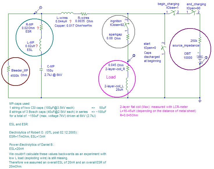
My high energy buddy Max B. performed some measurements on his 6kV / 150uF
MP-capacitor bank doing some metal forming experiments with a working coil
having an inductance of approx. 28uH.
The simulation in PSpice (fitting the measured voltage curve) gave us an
arc resistance of approx. 0.08Ohms and a peak current of 11.5kA.
ESL was estimated to be 0.02uH for the whole arrangement, ESR was estimated
to be 0.02Ohm for the whole arrangement, though these values have to be
calculated backwards after performing some exploding wire experiments.
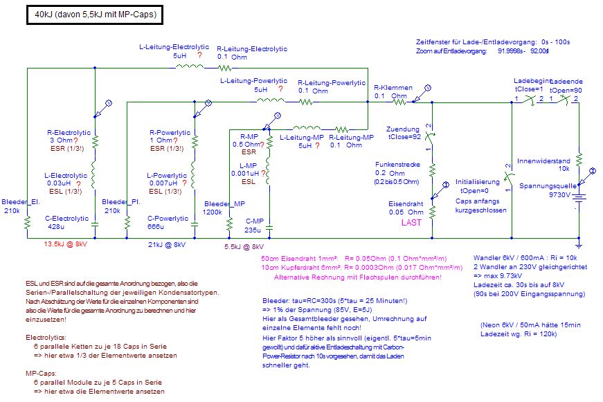
This is the circuit we simulated afterwards:
And this is the simulation result (fitted to the measurement):
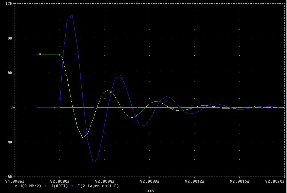
Actually, the measured voltage decayed a bit more than exponentially. That might be an effect of the arc resistance which is not constant over the time but depending on the charge flowing through the arc channel.
Additionally, a metal sheet was lying on the coil. Since the measured time constant of each cycle was equal (only the last one was a bit longer), we think that the current was completely gone until the sheet began to fly away.
I have no idea about the ESL and ESR of all the other MP caps up to now.
On the General Atomics Energy Division website (http://www.gaep.com/technical-bulletins.html) one can find a paper which describes the derating when higher voltage reversals are applied (http://www.gaep.com/tech-bulletins/voltage-reversal.pdf).
There is also a paper on safety
(http://www.gaep.com/tech-bulletins/capacitor-performance-and-safety.pdf),
where the following paragraph is taken from:
"One particularly violent failure mode that must be considered with large
capacitor banks that are designed to operate in air, as opposed to under
oil, is the ignition of a mixture of dielectric fluid and air after the capacitor
has ruptured. In this scenario, when the capacitor case ruptures, it sprays
the dielectric fluid into the air and then the arc caused by the internal
fault ignites the mixture." So please be careful and take appropriate measures
for that case when operating your capacitor bank!
Arrangement of the caps:
The best effect will be achieved with the highest voltage (and therefore highest current) by connecting all caps in series. This is ok for the electrolytics (see section on can crusher below). But the pulse caps from Aerovox and Bosch are different types (read ESL, ESR). It's not a good idea to connect caps from different vendors in series for HV or high current applications. Differences in surge impedance may result in accidental overvolting and failure of some caps followed by cascading failure of the rest. Also, lower voltages will be easier to cope with (think of corona). As described above, I'll build some modules rated 10kV and operated at 8kV. Each module will contain only identical caps.
With a 1" diameter 10 turn #10 AWG work coil, the peak current will be in the 50-75 kA range (according to Bert Hickman). It's hard to say what the lifetime of the caps will be since this will really be pushing them...
Charging circuit:
6kV neon sign transformer (rated 80mA, will be boosted to approx. 200mA) with bridge rectifier (2 stacked 6kV@100mA - diodes each leg) for 8kV charging voltage, small variac to adjust voltage.
Releasing the energy:
A) Firing the bank of MP-caps will be done via my EG&G GP-41B-25 triggered spark gap. It usually should be operated between 12kV and 36kV, can cope with a charge of up to 0.5 coulomb and peak currents of up to 50kA. Triggering will be achieved by a simple ignition coil and light dimmer circuit via two 0.5nF/30kV capacitors like Ross Overstreet suggested on his website.
B) Should the EG&G gap ever die, I can build a robust gap out of two 60mm spheres (approx 7.5mm for 25kV according to the table in he HV-book of Jim Lux). The gap setting can be tested (VOM with HV-probe) with a small capacitance and big charging resistor.
C) NEW: On the teslamania-website of Bert
Hickman I found a nice solution of a solenoid spark gap with moving contact.
The contacts are brought close together so that the voltage is sufficient
for breakdown. But they do not make physical contact. This way, no welding
together can occure.
I intend to use such a gap here to cope with the smaller voltage and higher
energy I have now available (not so good for the EG&G gap). Perhaps I'll
use some graphite electrodes on a pneumatic cylinder driven from a
small compressor. Setup will be: compressor, switching pressure gauge (to
switch compressor off via a contactor when a certain pressure is reached),
pressure regulator (with integrated particle filter), 5/2-way valve, pneumatic
cylinder (10bar). The valve will be pneumatically activated by a 3/2-way
valve which itself is activated pnematically when the operator turns
a pneumatic switch. This pneumatic switch is actually a manually
operated 3-way-valve. It assures that the tubing vented normally so
that no accidential activation can occure. This way, the operator only has
contact to two insulating tubings with a pneumatic switch at the end, no
electric conductive wires involved.
D) Another idea is to use a pressure dependent switch (low pressure) to activate the 3/2-way valve mentioned above. In this case, the operator only has contact to an insulating tubing with a rubber bulb at the end. One squeeze and the switch will be activated.
Experiments:
I'll do a series of experiments with different energy levels and different number of turns and different wire diameters to find an optimum in shrinking performance. I'll start with a 10 turn coil of #10 AWG.
Charging circuit:
I'll use perhaps a MOT (microwave oven transformer) with rectifier
(tbd., will include charging resistor for limiting
the initial current through the rectifier diodes) and variac
(to set the max. voltage) to achieve the
8000V.![]()
Varying the charging voltage, I'll perform the experiments with different energy levels following a logarithmic scale like the E6-series of resistors, with a factor of 1.47 between each step of energy.
Wenn die Bleeder zu niederohmig sind, erreichst Du nicht die volle Ladespannung an den Caps.
Wenn die Bleeder zu hochohmig sind, bringen sie nix mehr an Sicherheit (tau=R*C wird zu lang). Ich schlage deshalb vor, nur recht hochohmige Bleeder zu nehmen, so daß sie nur ein Wiederaufladen der Caps im Keller verhindern. Sowas in der Art von 1W pro kJ an 8kV ergibt dann 1.5MOhm an 8kV für ein 1kJ-Modul.
Am Beispiel meiner Aerovox-Caps: eine 4'er-Kette von Caps mit 2kJ Gesamtenergie an 8kV benötigen dann z.B. 700kOhm gesamt bzw. 180kOhm pro Cap. Die Zeitkonstante wäre hier: tau = R * C = 1.5MOhm * 1.34mF = 34 Minuten. Nach 5*tau = 2.8h wäre die Ladespannung auf 0.7% abgesunken, das entspricht 56V, was bei der Kapazität von 1340µF noch 2.1J entspricht. Da zuckt man immer noch ordentlich... (entspricht 100nF bei 6.5kV). Würde man die 10-fache Leistung in den Bleedern verbraten (430W in der gesamten Anordnung dann zuzüglich Meßgerät) wäre 5*tau immer noch 17 Minuten, bringt also nicht wirklich viel außer daß es den Ladevorgang ungünstig beeinflusst. Zur Not muss man halt > >2.8h warten wenn die Sicherheitsschnellentladung versagt. Die Bleeder müssen parallel zur Glimmlampe liegen, da die Glimmlampe ja immer nur ab ca. 65V leitet!
Aktive Entladung (immer auch nach dem Schuß) deshalb dann mittels Sicherheitsschnellentladung. Dafür habe ich Carbon(?)widerstände. So groß wie die grünen glasierten 200(300?)W-Widerstände aber eben im gesamten Material (Keramik + Karbon?) leitfähig. Hab sie noch nicht durchgemessen, aber da sollte was passendes dabei sein. Die 200W-Widerstände aus Vollmaterial reichen angeblich für 5kJ (siehe Text auf dieser website hierzu). Sollte dann aber grob überdimensioniert werden, da es ein essentielles Sicherheitselement ist. Für uns (43kJ) sollten wir bei Faktor 2 an Sicherheit also ca. 17 solcher Stäbe nehmen. Mal sehen was ich alles davon im Keller habe. Zeitkonstante etwa 0.1-1s stelle ich mir vor, also insgesamt 75-750 Ohm.
Ein Kurzschließen der Caps wäre auch zusätzlich sinnvoll vor Berührung der Klemmen. Hierfür manuell(!) per Zugseil betätigter Schalter um unabhängig von einer Serienschaltung von >>10 Zeitrelais zu sein ;-)
Messung des Stromes: Daniels Shunt mit Max seiner Faseroptik an Max seinem Speicheroszi
![]()
Steuerung:
sicheres Einschalten (Verriegelung: bei Stromzufuhr muß
manueller Kurzschlußbügel in Kurzschlußposition sein und
mechanischen Taster damit betätigen, siehe Daniel)
Signalleuchte Dauer-grün plus akkugestützte weitere grüne
Leuchte
manuelles Entfernen des Kurzschlußbügels
Signalleuchte Dauer-gelb bzw. eine akkugestützte weitere grüne
Leuchte geht aus
automatisches Entfernen des automatischen Kurzschlußes (Schütz)
Start der Aufladung durch Knopfdruck
Signalleuchte gelb getaktet (2Hz)
Zeitsteuerung (für feste Anordnung von xfmr und Caps) bzw.Ladespannungsüberwachung (variable Anordnung, ist aber fehleranfällig und dadurch gefährlicher). Am besten die maximal mögliche Ladespannung über Variac intern begrenzen!
Abschaltung der Spannungsquelle bei Erreichen der
Ladespannung, akkustische und optische Signalgabe (1s),
5s vor Start des Zeitfensters für manuelle Zündung
Start des Zeitfensters für manuelle Zündung
(max.30s)
Signalleuchte Dauer-rot
manuelle pneumatische Zündauslösung innerhalb Zeitfenster möglich
gezielte Schnellentladung (über Lastwiderstand)
der Restenergie 10s nach bzw. der Gesamtenergie bei fehlgeschlagener
Zündauslösung
(PROBLEM: um die Restspannung zuverlässig abzulesen muß Zeitfenster
lang genug sein, für sichere Entladung muß es kurz genug
sein!!!)
automatisches hartes Kurzschließen (Schütz)
5s nach Beginn der Schnellentladung
Signalleuchte Dauer-gelb
vor Berühren ist manuelles Kurzschließen
erforderlich um Signal (batteriegestützte Hupe, Blitzlicht) zu deaktivieren
(Schaltkontakt an mechanischem Hebelarm)
bzw. eine akkugestützte weitere grüne Leuchte geht wieder an
Signalleuchte grün,
bereit für erneute Aufladung
------------------------------------------------------------
weitere Sicherheitsfeatures:
allpolige Trennung der Anschlußklemmen (3Ph-Schütz mit 2Ph an einem Kontakt und eine Ph am anderen Kontakt bzw. besser 2 Schütze wovon nur eines zum Schalten unter Last dient (d.h. das andere schließt bereits vorher, z.B. bei Ertönen der Hupe 5s vor Auslösung)
Glimmlampen an den Caps (sieht man nicht in der gedeckelten Box...) => große Glimmlampe außen anbringen
Bleeder
analoges Voltmeter mit automatischer Bereichsumschaltung (Ladespannung 10kV / Restspannung 1kV bzw. 100V) außen an der Box
Kapazitätsmessung pro Halbmodul-Kiste (LCR-Meter geht evtl. nicht bis in diesen Bereich?)
------------------------------------------------------------
Weitere Features:
Digitales Voltmeter über Tastkopf (könnte wozu benutzt werden???)
Messung des Spannungs- und Stromverlaufes (Speicheroszi nötig!)
Filmchen mittels OlyC2020: 320x240@15fps (1/30s) bzw. 160x120@60fps (1/120s???) also 4x soviel Bildern (ca. 25 Einzelbilder dann vom BL-Ereignis, aber eben nur stark reduzierte Auflösung!)
Filmchen mittels K800i: Auflösung? fps? Belichtungszeit pro Frame?
Glimmlampe pro Cap => Anzeige von Spannung bzw. Restspannung
I got some advice from Bert Hickman:
Electrolytic caps do not support voltage reversals. In fact the dielectric will break down under any significant voltage reversal, helping to damp any ringing. Most pulsed applications with inductive loads (such as pulsed magnetizers) use a high current diode across the capacitor bank to handle reverse current during ringing.
If you're only going to explode wires, you probably
won't need a diode. However, if you ever plan on driving a coil (ring or
disk launcher, magnetizer, or coil gun) you'll need a diode. The current
rating depends on the inductance and resistance of your work coil and the
ESR of your capacitor bank. You may find the following tool (for coil gun
design) handy in getting a feel for the design parameters:
http://mgc314.home.comcast.net/ckt_sim/ckt_sim_main.htm
You'll want to use a power diode with a PIV that's at least the same or greater than the maximum voltage applied to the capacitor bank, and who's peak surge current rating (typically for 1/2 cycle of mains current or 17-20 milliseconds) is about the same magnitude as the peak reverse current - use the simulator above (or PSPICE) to estimate the peak reverse current.
I have no idea about the ESL and ESR of the caps up to now.
Another uncertain value is the resistance of the arc in the gap. For TC's, a value in the range of 2-3 Ohms is assumed. I'm sure that for the currents involved here, the resistance is much smaller (current is approx. two orders of magnitude higher, therefore the resistance should be at least an order of magnitude smaller).
Small signal measurements (with the use of a shunt resistor of small value compared to total resistance of circuit) will give the total resistance of the circuit (from max. current) and the total inductance can be determined afterwards from the decay (current over time). Both measurement require a storage scope for analysing single pulses. I don't have one, so I will use an f-gen to check the resonance frequency of the arrangement first. Knowing C this will also lead to the knowledge of L. Still don't know how to measure the gap resistance and the ESR of the caps....
Bert Hickman achieves some 10kA, with somewhere around 25kV and approx. 24uF (8.5kJ). So the total resistance (ESR of the caps plus arc resistance in the gap) according to the MGC-simulator (link above) seems to be somewhere in the range of 0.1-0.3 Ohms for his arrangement. Therefore I think I can assume somewhere between 0.1-0.2 Ohms for the arc resistance for my arrangement. According to the book "Rechnungsgrößen für Hochspannungsanlagen" (Heinrich Langrehr, AEG-Telefunken-Handbücher Band 9, 1969, page 111), the resistance of an arc shorter than 1m of length is in the range of 0.1-0.2 Ohms if the current is well above 500A (below 500A, the resistance is about 5 times this value). The arc resistance of my EG&G triggered spark gap is listed to be in the range of tens of milliohms. Of course, the arc channel has to have a certain diameter to achieve those low values of resistances. A free arc with currents above 500A will have a current density of approx. 500A/cm2 according to the book "Hochspannungstechnik" (Sirotinski, Band 1, Teil 1, VEB Verlag Technik Berlin, 1955, page 280). For those high current arcs, the diameter (in cm) of the arc channel is 0.057*sqr(I) according to Sirotinski. Assuming a current of 30kA, the electrode diameter of the gap should be in the order of four inches! Since the distance of the electrodes is much smaller (only some mm for 4kV assuming nearly parallel planes with smooth edges), the diameter can be smaller, to. But it should be not to small for achieving a low resistance in the channel.
Suitable values for the shunt resistor will be: 1mOhm for real discharges (50kA := 50V) and 100mOhm for small signal measurements (50 := 5V).
Releasing the energy:
The bank of electrolytics will be fired with the help of one of the following mechanisms:
1) Directly with a big contactor. It was originally for 3 phases each 660V~ which equals 3x660Vx1.41=2800VDC (400A?). It was made to industral standards and therefore could cope with a good overload ;-) Daniel tested them successful (two contacts wired in series) with 12KVeff without arc-over. Many thanks again, Daniel, for giving me two of those big contactors! Daniel used a clever circuit with timing relais. The big contactor was switched by another one which also switched the discharge resistors in after the big bang. Therefore the caps will be discharged even if the contacts of the big contactor will weld together one time.
2) With a vacuum gap. Changing the pressure results in a different breakdown voltage. No moving contacts, nothing can weld together.
3) Moving contacts (spring loaded, hold with electromagnet before firing), only proximity (no direct contact). 2kV will be ~2mm, 4kV will be ~4mm. Electrode material will be graphite, copper, brass or steel. Ich dachte Anfangs daran, die bewegliche Elektrode mit einer Feder vorzuspannen und mittels Elektromagnet zu halten. War mir aber dann zu unsicher. Ich muss mir das mal durchrechnen um zu sehen ob es überhaupt was bringen würde im Vergleich zur elektrischen Dauer der Entladung.
4) Wie wärs mit ner Druckluft-Funkenstrecke? Einfach druckfest aufbauen (dickes Lexan als Isolator, Rest alu) und die Elektroden so einstellen, dass es bei normalem Druck zündet, bei erträglich hohem Druck (5bar?) aber zuverlässig isoliert. Dann mit Druckluft aufpumpen bis 8Bar, Caps laden, Druck ablassen.
Safety circuits:
Planned arrangement of all our (Daniel, Toni, me) modules for the real
big bang:
That sums up for 1.36mF@ 8kV which represents 43.6kJ electrolytic power. (8.6kV will result in 50kJ, 8.9kV will result in 54kJ - that is 3 M&M's Choko).
(I still have to update the next image, the values of caps are wrong)
The whole thing will eventually be charged by my 6kV/100V-voltage
converters:
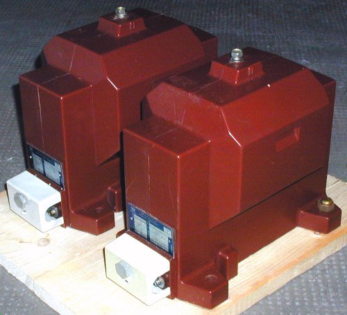
or 3 MOTs connected in series (not so heavy as the two monsters above).

![]()
![]()