some words about neon sign transformers...
![]()
The neon sign transformer is the xfmr most often used by beginners. For the starting coiler, they have many advantages which will be explained on this page. Neons are not as robust as power distribution xfmrs (called pole pigs in the USA) or measurement xfmrs, but with the right treatment, they can also last very long.
Some words about safety: electrocution is the number one danger. The neon sign transformers have typical voltages from 6000 - 15000 volts. Its made even more dangerous in the primary circuit of a Tesla coil due to the storage of energy in the main caps. A current of 30mA can kill you!
Some more info on neon signs can be found here: http://www.neonshop.com/software/software.html (calculator etc., link not tested up to now!)
In many of the discussions on the TCML it is told that one should go to neon sign shops (they can be found via the yellow pages under neon signs or signs). Neon sign shops usually collect the old xfmrs for scrapping them when they install new signs. Most of the old neons are still good (and even the dead ones can be repaired in most cases, so collect also the dead ones!). By going into 15 or more shops, I collected many neons just for free. One shop offered me also to take some "short" pieces of neon cable for free, at home I measured that the total length of the pieces was 246' (75m) and all were longer than 26' (8m). Asking again and again in the shops where I've been successful, I collected an equivalent of 5kW/8kV so far. Key components of a successful acquisition: be friendly, tell the guys what you want to do with their neons and bring some images of a running coil (somebody elses coil if yours isn't running at this time) with you.
It seems, that here in Germany only 8kV-neons, of course with a center tap
:'-( , can be found. In an old book from 1963 it is stated that the
VDE0128 allows 15kV, but apparently they changed this later down to 8kV.
Due to the regulations (equalization) in the European Community it seems
that there will be xfmrs up to 10kV on the market now, though this will possibly
not be the old robust ones but more likely the modern fragile electronic
ones. This is a bad situation, because with such a low voltage, the primary
capacitor has to have a higher capacitance as usual. This leads to a small
primary inductance (remember
fprim=fsek) and so to a less effective
system because of higher gap losses.
Another high voltage source are oil burner ignition xfmrs (OBITs). On some scrap yards one can find OBITs with ratings up to 10kV and up to 500W with NO centertap! So you can combine them to a nice 12-15kV source (by the use of a variac) which allows you to reduce the tank capacitance and increase the tank inductance for a more efficient system. More than 15kV is not recommended for the beginner (corona problems, breakdown of caps etc.). Some german OBITs are only 5kV and have a limited playtime. They can be paired to deliver 10kV. The sad thing is, that one of them costs around 6US$ and delivers only 18mA. For my 540W@10kV-source made out of 6 of them, I paid 36US$ :-( But they are very small, easy to handle and great for a mini coil, like Vitamini.
For really high power coils, one can acquire a power distribution transformer (called 'pole pig' in the USA) or something similar (potential xfmr like industrial voltage measurement xfmrs). It is a must to limit the input current into these BIG xfmrs or one will take the whole neighbourhood into the experiment. Current limiting can be done with a resistor (oven elements from second hand) or an inductor (e.g. arc welder or some windigs of HEAVY wire on a big EI-core with suitable air gap) or with a combination of both. A rotary gap in series to the static gap is advised at this power level. Main problem here: it is very hard to find such xfmrs here in germany. I have some more info on potential xfmrs on my 10"-coil page, infos around my homemade ballast inductor can be found here.
Neons and OBITs (oil burner ignition xfmrs) are current limited by design. That means, no external current limiting is needed. To understand this, lets have a closer look on a design widely used here in Germany. Here we call the neon sign xfmr "stray field xfmr". In opposite to a standard xfmr, the stray field is here intentional. The core looks like the number eight in digital writing (seven segment display...). The primary windings are on the lower 'o', the secondary windings on the upper 'o'. The difference to other xfmrs is the horizontal bar '-' in the middle. A fraction of the flux generated by the primaries is going through that bar. So not all the flux is going also through the secondaries. The flux in the bar is called stray flux. Electrically speaking, the stray field xfmr can be seen as a normally xfmr with a choke coil in the feed line to the primary. The inductance of the choke coil (the shunt) is called stray inductance. So the maximum input current into the xfmr is limited by this stray inductance. Most old neons in Germany have a movable shunt (newer ones and also most neons in the USA are housed in a metal box filled with tar, look at the repair section to see how they can be freed from the tar). With the screw in the middle of the bar it can be moved out of the plane of the core (the '8') so that the stray field is reduced and therefore also the choke coil inductance.

The maximum input current therefore can be adjusted. For Tesla coil use,
we can screw the bar extremely out as we usually only have short runtimes
(low duty cycle => higher pulse power possible until thermal destruction
takes place). As Martin wrote on the GTL, you can suck about 2-2.5 times
the rated current out of such a modified neon xfmr for short times (<15
min). In this case you waste 4-6 times more power in the copper of the xfmr
windings than in its normal duty. It is not known, how fast (and effective)
this heat can be brought to the outside of the windings, so there might build
up some hot spots which you can't notice by touching the outside (never touch
a neon if it is plugged in!!!). To measure the average temperature,
you can check the resistance of the secondary windings, which is temperature
dependent. The coefficient of temperature for copper is ct=3.928e-10/°C.
The formula for the temperature rise is
Rt=R20*(1+ct*dT).
At 20°C the specific resistance of copper is 0.0176
Ohms*mm2/m, so for a known diameter you can get the length of
wire (not really needed for this calculation on temperature rise, but sometimes
helpful for other calculations).
You can measure the R20 and if the Rt is measured after a certain runtime,
dT and T=20°C+dT can be calculated by the formula
dT=(Rt/R20-1)/ct.
In an old book I found this diagram about the decrease of the secondary voltage with increasing secondary current:
From this we learn that the power used by the resistive (!) load is NOT the open circuit voltage (Uo) times the short circuit current (Is) though these are the values given on the plate of the xfmr. It is only about 40% of this! The optimum load is matched to the output impedance of the xfmr: Z = Uo/Is. In this case with a load of 6250V/66mA=95kOhm maximum power is transferred. The input power in VA of a compensated neon xfmr in Tesla use is mostly about the same as the rating on the plate which is surprisingly Uo.Is. This is because of the resonance condition at mains frequency, the neon is usually set in by connecting a matched capacitor to its secondaries. We all love the additional current and higher voltage produced due to this resonance condition, but they are also limiting the lifetime of the fragile neon transformer. So you should always use a safety gap to limit the voltage to its original value. Since most Tesla coils run only with short duty cycles, the increased current will be not so critical.
Current is not so critical to NSTs as the voltage is. The NST is designed to run at a much lower voltage of about 800 volts when loaded by the neon tube. The high voltage is just a short burst to light the tube. The constant HV on the secondary might break down the tar in TC usage over time.
If you measure the resistance of the cold windings (that is _before_ you pump a lot of current through them!) and know their temperature (give them a few hours in the room you want to perform the measurement in), then you can calculate the AVERAGE temperature of the winding after a certein runtime by simply measuring the resistance of the winding again. Maximum temperature of a hot spot inside the winding is 90°C! Therefore you should not go beyond 65°C for the average winding. Be sure to safely discharge all capacitors and remove all connections to the xfmr before doing this measurement! If we assume e.g. a room temperature of 20°C and a resistance at this temperature of "Rhot=R20", then the elevated temperature "Thot" after a certain runtime can be calculated by the formula
Rhot = Rcold * [1 + alphaCu*(Thot-Tcold)]
which leads to
Thot = 20 + [(Rhot/R20)-1]/alphaCu
with
alphaCu=3.928e-3(1/K)
Data and formula are according to "Dieter Nührmann: Das große Werkbuch Elektronik, Band 2".
You can't connect two neons in series to double the voltage. But you can parallel neons which have the same voltage for higher current. If you'll connect them in series, the isolation between the core and the inner windings (where the centertap will be connected) will most propably break down. Your neon will see RF in TC application, this is a bad situation for the weak isolation. Please consider that the isolation of the inner windings against the core is not necessary in standard useage because the centertap will connect this winding directly to the core. If the isolation will burn out, your neon will be dead because you can't repair a neon in the inner windings.
This scheme shows the WRONG way of connecting centertapped xfmrs. The centertaps will be on +/-HV against the grounded core (you MUST ground the core to the line-gnd!!!), therefore the isolation will burn out.
              _+HV_____________________________o
 o__________ (
   l   |    )(
   i   |    )(___gnd
   n   |    )(
 o_e__ | ___)(
       |  |  (_-HV___
       |  |          |               W R O N G !
       |  |          |__________
       |  |    _+HV__|          |
       |  |__ (                 |
       |     )(               -----
       |     )(___gnd          ---
       |     )(                 -
       |_____)(
              (_-HV____________________________o


Centertapped xfmrs should only be connected in parallel
(primary and secondary coils) like shown here:
                   __                               __
            ,--+--|__|-----+---------o +HV o----+--|__|---o
o---+-----,(   |           |                    |
 l  |     )(   v           |                    |
 i  |     )(______________ | __               -----
 n  |     )(               |   |              -----
 e  |     )(   ^           |   |                |
o------+--'(   |  __       |   |                |
    |  |    '--+-|__|---+  |   |                |
    |  |                |  |   +-----+----------+
    |  |          __    |  |   |     |          |
    |  |    ,--+-|__|-- | -+   |   -----        |
    |  +--,(   |        |      |    ---         |
    |     )(   v        |      |     -        -----
    |     )(___________ | _____|   line       -----
    |     )(            |           gnd         |
    |     )(   ^        |                       |
    +-----'(   |   __   |                       |   __
            '--+--|__|--+-------------o -HV o---+--|__|---o

If you get no output voltage, simply reverse one set of
connections of one xfmr (to change the phase by 180°).
Here is a text I downloaded somewhere (please let me know if you are the author!) from the internet describing the procedure: If you parallel some more xfmrs, how you determine the polarity of the transformer so you can hook up all of the +HV and -HV together? Well, at first you should connect their cases together and then to a good AC (RF) ground. Leave the center tap connected to the case! Then wire the primaries in parallel and attach a stiff wire with very good HV insulation to the first transformer's HV terminals. Use some insulated rods to route this hot wire to the next xfmr. Bend the wires so that they nearly touch the HV terminals of the second xfmr. When applying a voltage (use a variac as always) to the xfmrs, you should get NO high voltage arc between the right phased HV terminals. You'll get an arc to the one that is OUT of phase, and hardly any arc at all to the HV terminal that is IN phase. If the phasing is the opposite of that desired, then simply rewire the parallel connection wires that join the first transformer to the second. In other words, leave the first transformer alone and just exchange the two primary wires on the second transformer ONLY. Repeat with all other xfmrs.
High voltage filter board:
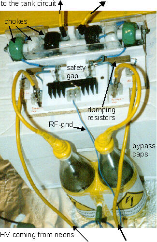
Neons should be protected with a high voltage filter board. It usually consists
of bypass caps, a safety gap and damping resistors. The filter protects the
HV windings of the high voltage transformer from the RF generated in the
coupled primary and secondary circuits. This RF can easily cook the insulation
of the transformer which results in breakdown. The bypass cap with the safety
gap across it is in parallel to the HV windings of the high voltage xfmr.
The damping resistors in each high voltage line to the tank circuit are located
before and after the bypass caps.
To be effective, there have to be many losses in this filter circuit. Wattless losses in the bypass caps decrease the usable amount of current as well as resistive losses in the damping resistors and the chokes. Of course, the damping resistance has to be high to be effective. Therefore, the filter board has to be designed new for every different power level. I myself go for 5% to 10% losses in the filter. This way, I never had a failure in my xfmrs so far. The best way is to test the filter board with a function generator hooked up to the filter output and an oscilloscope hooked up to the filter input. It is important to connect the HV-xfmrs also in this test! If there should be any resonance peak, one should redesign the filter board. Click here to get more information about the HV-filter board.
 |
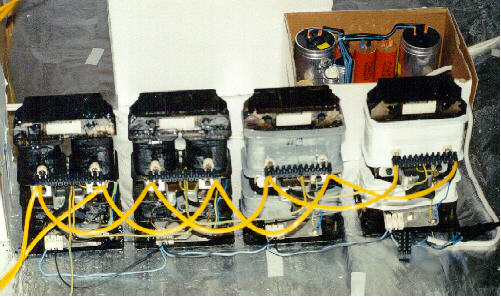
Specs of the filter board I used on my first TC (the 2"-TC): Size 10"x10" (25cm x 25cm). There are 6 chokes (Chokes are no longer recommended!): two iron powder cores with 250 turns which gives two times 6mH and four ferrit cores with 77 turns which gives four times 34mH so that each feed line has an inductance of 74mH. The dimensions of the choke cores are D=1.4" (36mm), d=0.9" (22mm) and thickness h=0.6" (15mm) (cross section is then 0.6"x0.28" (15mm.7mm)). I used two nearly indestructible 0.56nF glass bottle bypass caps, a safety gap, two 260Ohm/11W resistors which is enough for short run times at 2600W up to one minute. A complete circuit diagram can be found here. The two glass bottle caps are now replaced by 6 ceramic disc caps (with bleeding resistors). |
Type of gap:
You can use static gaps with neons as well as an asynchronous rotary gap
or a synchronous rotary gaps. At all types of rotary gaps, a well adjusted
safety gap has to be used, the phase of the synchronous gap has to be adjusted
very carefully (lot of work and measurements!) so that no damage will be
done to the xfmrs.
The first thing to do with a new acquired used (sometimes very old and rusty)
neon tranny is to check if the wire insulations and the windings look
mechanically and electrically ok. It is a good idea to use pressurized air
to blow the dust off first. Next check the resistance of the windings.
The primary should have no contact to the case or the secondary. The resistance
between each high voltage terminal and the center tap (core, case) should
be equal (+/-10%). If one winding is open circuit, the neon can't be repaired
in most cases. If the resistance of one winding is to low, an arc has occurred
between different layers of the winding and left a carbon track in most cases.
If everything seems ok, then perform a low voltage electrical test: apply
a low level test voltage (9-24VAC @ line frequency) between the two HIGH
VOLTAGE TERMINALS (that's the neons secondary!). Now you should measure 1/2
of the voltage that you apply between each high voltage terminal and the
ground (case, center tap).
As a last step, make a small spark gap between each high voltage terminal
and the grounded centertap. Use the control panel of your Tesla coil (you
know, the one with the meters, the fuses, and the multiple switches) and
your variac to connect the neons primary in a save way to the line voltage.
Be sure to place the neon on an isolated support - and please: don't place
it on the carpet in your living room, in case of a short circuit a flame
could come out of the neon tranny... DON'T TOUCH A NEON IF IT IS PLUGGED
IN!!! When bringing the voltage up (slowly!), watch the input current and
hear on any abnormal sound coming from the xfmr. Once the arcs forms between
the two high voltage terminals and the center tap electrode, they should
be of the same intensity and colour.
Some neons come in a housing (metal box) filled with tar. If these neons
are shorted, this is most often by carbon tracking
(an arc inside leaving a carbon track in the
tar). As Gary
Weaver suggested in May 1997, they can be repaired simply
(if the primary and secondary coils are still
good) by putting them in the kitchen oven at 200°F (~90°C)
(put an old pan under the neon in case some tar leaks out). Increase the
temperature in steps of 50°F (~30°C) every hour until the tar melts
(different temperature between each manufacturer, up to 300°F
(~150°C)). If your wife didn't allow that procedure to you, you can
also use a BBQ-grill (closed type with thermometer). Or get one of those
"extra eyes" standalone heating elements, turn it on (outside) and leave
the tranny on there for some hours. As a result the carbon will
be diluted in the melted tar and so the short circuit should be removed.
Obviously also all cracks in the old tar are removed this way and after cooling
down the neon will work fine again. If not - visit the local sign shops and
beg for another unit.
A newer posting from Gary Weaver describes the method of de-tarring and unpotting
a neon xfmr very clearly:
http://www.pupman.com/listarchives/2000/February/msg00552.html
To improve the output power of a neon tranny for Tesla coil use, one have to open the box and unpot the xfmr. With the method above, you can simply pour the molten tar out. Else you have to remove the tar carefully with a hammer and a chisel. Lift the transformer out of the case. First you have to measure the short circuit current of the neon. Connect an amp meter to the secondary coil. The meter acts like a short circuit and will therefore survive as the voltage will drop near to zero. Don't touch the meter or the neon when the neon is plugged in!!! Remove some metal plates of the shunt and check the current again. Remove enough plates to get the desired current. This way the current rating can be increased to 150-175% of the original value for Tesla use (remember the short runtimes). It is not necessary to fill the box again with tar, xfmr oil is the better choice. This is because we deal with RF where the tar is very bad but oil is still good. But you also can use it dry. Or try vaseline (melt it carefully and pour it in) or HV-jelly (thread in may'99 on pupman).
In this section I will show you some measurements I did on my first MicrowaveOvenTransformer. This is a very deadly device: currents of up to 2A at 2400V! So please be careful when playing with such a thing!!!
Here you can see why a MOT will die in a Jacobs ladder test. Yes, MOTs have a magnetic shunt as neons have. But MOTs are not designed to have a complete short circuit on the secondary side (like the neon tube is on a neon xfmr), at least not all of them. When you look at the uWave-page of Chris Hills, you can see that the current to the magnetron has to pass a capacitor and is therefore limited by its capacitance. The shunt in the MOT is to weak for TC work and you definately need additional ballasting on most MOTs!!! In my case, the oven had two capacitors in it (0.35uF and 0.49uF), limiting the total current (considering the magnetron as a short circuit) to less than 630mA (open circuit output voltage of the MOT is 2.4kV). The fuse on the secondary side was rated 5kV/600mA. So I now have a transformer for TC-work which will do 1.5kVA ((2400V/0.6A) continiously(!), for some short time runs (<30s) you really can double the amperage (for 3kVA) if you allow a suitable cool-down time inbetween. All measurements are done without power factor correction up to now!
(click on image for full resolution!)
![]() MOT measurement with PFC to
be done...
MOT measurement with PFC to
be done...
back to top of page
![]()
![]()