How I build my 200BPS synchronous rotary spark gap
![]()
![]()
| TOC:
|
 |
Well, as described on my BlueThunder page, I want to pump about 5kW through my setup. Even with only 15% losses in the gap (this value is only speculation!), this works out to up to 750W. So there has to be a significant cooling at the gap. Perhaps a good massive and heavy blown vacuum gap would have been sufficient. But hey, a rotary is way cooler!
The static gap will perhaps not quench good enough (though I bet it will, as I have seen a standard muffin fan type RQ/RH cylindrical gap of a fellow coiler perform very well with my pigs), so I'll build an additional synchronous rotary spark gap (SRSG).
As described on Terry's website (hot-streamer.com/TeslaCoils/Misc/syncmot.zip), one has to grind some flats on the rotor of an ansynchronous motor to make it run synchronous. There have been some discussions on the TCML about how deep the flats should be made. Perhaps the flat is not the ideal shape, in January 2001, a new disussion about this started on the TCML.
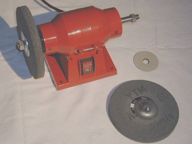
A guy called David wrote on 1st. of June 2000 on the TCML ("economical rotary gap motor") that he acquired a bench grinder ("Black&Decker", 40$US) and modified it into a rotary gap. He reported that it functioned very well. It cames that just at the day I've read this post in the TCML archive, I found such a bench grinder (brand "parkside") in the supermarket below my flat - and it costed me only 29.90DM which was about 15$US at this time! A quick test of the thing showed a lousy torque (only 150W...), but excellent bearings (no movement to any side possible as in most other motors like angle grinders)! Definitively an advantage for coilers. The housing perhaps can be easily modified for holding the static electrodes. If I get promising results with the planned vacuum gap, the grinder remains a grinder, else it will be my first try to build an asynchronous rotary gap. I guess the 24 moths of guarantee will not be valid if I modify the bench grinder into a rotary ;-)) BTW, David gets 3m long arcs with his 10kVA pole pig and the described rotary - the dimensions of his garage are limiting the arc legth.
After reading more and more about rotary gaps, I think I'll build a 200BPS synchronous RGS out of the bench grinder. Alternatively, I have an old motor out of a washing machine sitting around here (have to look up the rpm & power rating), which could also eventually be modified for an SRSG.
Of course I will use a proper set safety gap in parallel to the RSG. For fault current limiting purposes, I'll place two big (220W) 47Ohm resistors in series to the safety gap.
Stefan Bauer made a very good design which was also put into action by Kurt Schraner. Both achieved excellent results.
technical data of my bench grinder (double shafted motor):
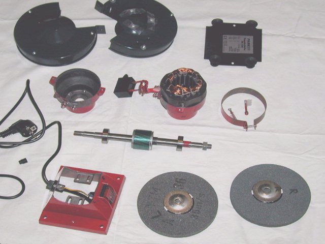
"Exploded" view:
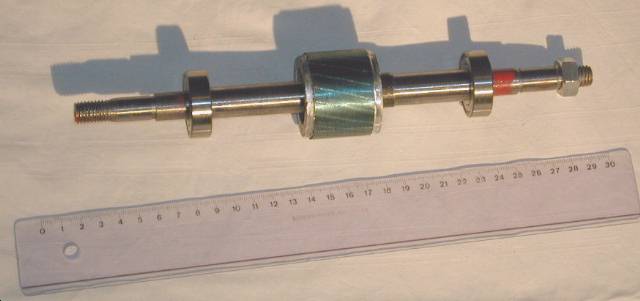
with 30cm-ruler for size comparison:
the bearings (they are stamped with "XEZ 6202Z", anybody knows what this
means?):
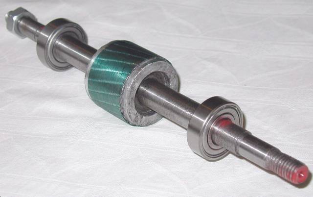
where the flats will be grinded:
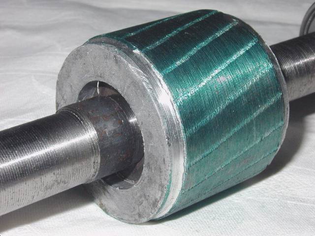
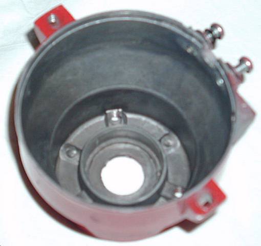
here in this shell sits the bearing:
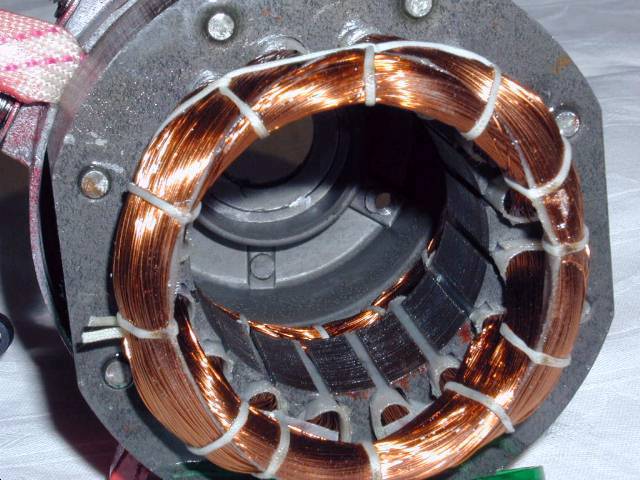
the other side, view through the winding and poles:
Luckily, I got all the parts back together and the grinder works just like
before:
Excel-Sheet: tc/rgap/j.xls comparing the inertia of the rotary with the inertia of the bench grinder (=> how fast will the rotary come to speed)
| http://home.t-online.de/home/Stefan.Binder/
Flexigap:
disk:
screw:
velocity: 310 km/h |
Original carborundum (emery ) disk: 150mm diameter,
16.5mm thickness, 610g each.
Hubs: 54mm diameter, 170g all together.
Pertinax: 150mm diameter, 10mm thickness, 228g each / 200mm diameter,
10mm thickness, 405g each.
3000rpm, 2 flying electrodes, 4 fixed electrodes for 200BPS (connections can be changed for 100 BPS).
![]()
Material: Tungsten with Lanthanium,
diameter 8mm,
max. 4 rotating electrodes (length 50mm),
max. 6 static electrodes (length 25mm)
for up to 600BPS (200BPS = 2 rotating + 4 fixed electrodes)
![]()
![]()
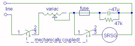
Phase shifter (electrically adjustable phase)
for my SRSG:
(circuit idea by John Freau, see TCML-archives of December2000 and
January2001 and his website
http://hometown.aol.com/futuret/page3.html)
The mechanical phase of the motor can be adjusted (electrically and remote) for maximum spark length by the use of a variac (turn the knob). I have not done tests on my own up to now, but others report great success with this method.
Please see the following text for dimensioning of the
components!
The variac in series to a properly sized capacitor allows the phase of the SRSG to be adjusted to the 50Hz line frequency over a 90 degree range while the coil it running. Smaller variacs (current wise) have a higher inductance (typically 0.2-4H), it seems that there is no reason to use a variac much bigger than the motor plus the cap require (cap requires more current if you use a high power variac which has a low inductance, up to 300VA for a 20µF cap at 230V). The capacitor has to be matched to the variac so that XL=2*XC (typically 47-2.5µF) so that you can adjust the phase to both sides (leading & lagging). Finetuning of the capacitance can be done with respect to the motor so that no resonant rise (max. +5V) of the voltage across the motor can occure at any setting of the variac. As always, the use of a bleeder resistor on the cap is highly recommended! Be prepared that the moter will draw up to 40% more current when modified for synchronous operation, you might have to reduce the voltage for temperature reasons. Another safety feature is the fast blow fuse in the line to the cap. If you forget to connect the motor or the motor fails (or its connection), a resonant rise would occure and very high voltages would develop at the variac and capacitor. The resulting high current will blow the fuse in this case and protect the components and the operator. Select the fuse for the current the cap usually needs, not much more. There are two mechanically coupled switches drawn in the schematic above to switch the rotary off. This is done to prevent dangerous self-breaking action which could occure at larger motors, especially if the capacitor is too large. The self-breaking action would stress the motor mechanically. Of course, the phase should be set mechanically to a ballpark setting before you start the SRSG the first time. Be sure to set the variac at minimum inductance when the motor is started! You could add a timed relay that does this automatically at start up (you will start the SRSG before applying HV anyway).Oh, btw, it seems normal to measure a strange distorted sine wave voltage across the motor. A reference signal from the mechanical position of the electrodes could be achieved by the use of a photodiode and a laser or by winding a pickup coil (good idea from Finn Hammer). Use a dual trace o'scope to see the phase difference between the two signals.
The phase of one pair of fixed electrodes (if you run the SRSG at 200BPS) can be adjusted separately for equal bangsize at 200BPS, have a look at Richie Burnetts website for details (perhaps I'll make use of a big "lazy Susan bearing" so that I can rotate one set of electrodes).
![]() more data to be added when
my SRSG is running...
more data to be added when
my SRSG is running...

![]()
![]()