Be careful and watch your step, this page is really
a construction site up to now! |
Blue thunder (aka "The BIG one") - my planned 10"-project
(design data: 5.3kVA pig power for 2.8m spark length!)
Be careful and watch your step, this page is really
a construction site up to now! |
My 30A(peak)-setup will contain:
This way I can adjust the power (via the inductive ballasts), the voltage (variac, gap setting in case of the vacuum gap) and also the BPS (gap setting and ballast) which, of course, is not independent from the other parameters like the capacitance of the tank capacitor.
With this setup, I should be able to pump up to about 5kW into my big TC, which should result in up to 3m (perhaps even a bit more) spark length! Perhaps this system will have the capability to be driven with up to 15kW (3 phase, rectified neons for a DC driven coil system), but this still has to be calculated. A member of the GTL achieved 2.8m sparklength with his 200x40cm coil. He used 9 banked neons where he measured 7.5kV open circuit voltage and 990mA short circuit current.
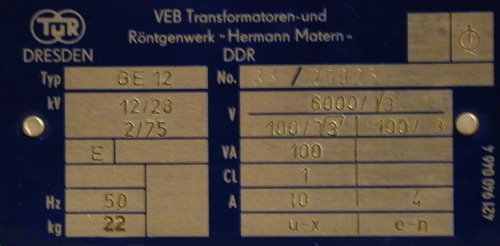
Its pole pig time! Ok, they are not really pole pigs (power distribution xfmrs) but measurement xfmrs (voltage xfmrs, 100V/6kV) instead. But because of the fact that they behave like pigs (no internal current limiting) and that they are nearly as robust as pigs, I'll call them pigs (this also is shorter than their real name...). Todays question: how much resistive/inductive ballast will I need for using them safely in TC (or Jacobs ladder) application? I want to limit the power (current) in three steps (7.5A / 15A / 30A at 250V coming from the variac).
Instead buying an arc welder for limiting (proned to overheating), I found a very promising method on Richie Burnett's website. He describes a commercial buildt inductive ballast which allows the current to be set at anything from 1A to over 40A rms by adjusting the air gap in the EI-core. The links to Richies descriptions are: <http://www.staff.ncl.ac.uk/r.e.burnett/ballast.html#inductive>, <http://www.staff.ncl.ac.uk/r.e.burnett/parts2.html>, <http://www.staff.ncl.ac.uk/r.e.burnett/inductr.html>. These descriptions of Richies ballast sounded very promising to me, so I decided to build similar ones on my own:
More on this subject can be found on my ballast page!
Why I made a second inductive ballast? Well, I achieved very satisfying results
with my inductive ballast #1 and I wanted to be able to switch between them
to adjust the current limiting by a simply turning a knob (rotary switch).
OK, an arc welder would do the job, too, but arc welders are usually not
designed for the current I like to pump throught the ballast in the future
so they would be prone to overheating. I decided to make a sophisticated
circuit to use the two ballasts either in parallel or in series or only one
of them at a time, so I'll be able to limit the current to 7.5A (both inductive
ballasts in series), to 15A (only the big ballast#1) and to 30A (both in
parallel). This required a rotary switch consisting of at least 3 positions
(4 if you want to have an additional "off" position) and four layers. You
will need two layers with one "connect" (and the other three "open") contact
and the other two layers with the reverse logic (three "connect" and one
"open"). Most switches will only provide "one connect and the other open"
contacts, but you can use two heavy duty relais (in german they are called
SCHÜTZ, I'm sorry not to know the english word here, perhaps it is
"contactor"?) to invert two layers (but be careful: from the safety point
of view, the "off" position is not safe any more as one SCHÜTZ could
fail and let loose so it will make contact).
Here is the circuit diagram (switch positions are 0/1/2/3, contact
"o"=open,"c"=closed; the numbers in green are the contact numbers that can
be found on my switch - yours may vary, perhaps you have to adjust the positions
of each layer, perhaps you even have to invert the switches which are labled
7/8 and 1/2 in my scheme.):
                                                 off
        o                                        +--o     ,
        o \                    ____   __         |    ___/_
        o  *---------------+---XXXX--|__|----+---+---|__/__|-
   +----c                  |   ib#2  1.25    |     min /   max
   |   10/9          o     |         t.b.d.  |        * 2.07
   |              +--c \   |        (0.625)  |        |
O--+              |  o  *--+                 |        +--------o
   |              |  o                       |        |
   |              |  11/12     o     +-c     |        |
   |  ____   __   |          +-c \   | o \   |   __   |
   +--XXXX--|__|--+----------+-c  *--+-c  *--+--|__|--+
      ib#1  1.25             +-c     +-c        t.b.d.
            t.b.d.           7/8     1/2        (2.5)
           (0.625)

switch position 1: off
switch position 2: ib#1 and ib#2 in series
switch position 3: ib#1
switch position 4: ib#1 and ib#2 in parallel
t.b.d. = see update 04'2002 below (resistive ballast)
|
As you can see, I added a bit of resistive ballast, too. The best values
("smooth" performance of the TC) have to be found by experimentation, given
data is what my feelings say at the moment (and what my big crane resistor
consists of....). I plan to measure the current going to and the voltage
over the pigs. Additionally, the voltage over the inductive ballast and the
temperature of the pigs.
There are two more layers left on the rotary switch. I'll use them for indicator
lamps '(x)' on my control panel showing me how
much current is available at the moment (only for 15A and 30A, the 7.5A-setting
will not be indicated by lamps):
           o  13/14
           o \
   +--(x)--c  *--+
   |  15A  o     |
   |             |
O--+       o     +--O
   |       o \   |
   |       o  *--+
   +--(x)--c  19/20
      30A

switch position 1: off
switch position 2: ib#1 and ib#2 in series
switch position 3: ib#1
switch position 4: ib#1 and ib#2 in parallel
|
The technical details of my inductive ballast #2 can be found on my ballast page!
After I buildt the inductive ballasts,
I collected some info on saturable reactors (did an altavista-search).
More on this subject can be found on my ballast page
I plan to add 1.25 Ohm to each inductive ballast. The intrinsic resistance of inductive ballast 1 is 0.14 Ohm, the intrinsic resistance of inductive ballast 2 is 0.527 Ohm. Each ballast will see 15A, so the power loss in the resistive ballasts will be 281W. At full power (30A total), the resistive losses therefore will sum up to 32W+281W+119W+281W=713W, this is approx. 10% of the total power the system will draw.
| More data will be placed here soon, I still have to take the measurements... |
Update 04'2002:
on the hamfest in Neuburg'2002 I found a variable resistor of 2.07Ohms at
10A. If blown with a big fan, It should take at least 15A (or even 30A for
short runtimes). I plan to add the variable resistor to the circuit so that
I can find the "sweet spot" in resistive ballasting. The value of the
planned 1.25Ohm-resistors will be decreased (preferable down to half of the
value). In parallel to the 2.07Ohm variable resistor, I will place another
power resistor (2.5Ohms) to lower the value of the total variable
resistance:
position variable parallel total total resistance resistance resistance resistance [%] [Ohm] [Ohm] [Ohm] [%] 0,00 0,00 2,5 0,00 0,00 0,10 0,21 2,5 0,19 0,17 0,20 0,41 2,5 0,36 0,31 0,30 0,62 2,5 0,50 0,44 0,40 0,83 2,5 0,62 0,55 0,50 1,04 2,5 0,73 0,65 0,60 1,24 2,5 0,83 0,73 0,70 1,45 2,5 0,92 0,81 0,80 1,66 2,5 1,00 0,88 0,90 1,86 2,5 1,07 0,94 1,00 2,07 2,5 1,13 1,00 |
The additional OFF-position of the poti should be conneted to the MINIMUM-position, else the resistance in this position would be the full parallel resistance!
Update 07'2002:
I found a second one (identical) on the HamRadio hamfest in Friedrichshafen'2002.
Some technical data of the two big measurement
xfmrs:
Here are some pics of the pigs!
I recently acquired a set of two smaller dry measurement xfmrs:
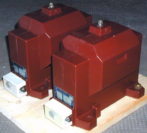
Up to now, they service as a power supply for my Jacobs Ladder.
| description of the measurements I plan to perform
on my pigs (sorry, only in german up to now):
Aufgrund der Sättigung von Ballast ib#1 sollte dessen Gap eng eingestellt werden, dass in allen Betriebszuständen unter Verwendung eines geeigneten resistiven Ballasts (Spannungsabfall!) bis zur Maximalspannung (250V vom Variac) der Maximalstrom von 15A nicht überschritten wird. Für die Regelung ist das Sättigungsverhalten sogar positiv zu bewerten, da man dann die letzten Ampere aus dem Setup mit dem Variac herauskitzeln kann, ohne die Spannung wesentlich ändern zu müssen (man spart sich also eine gesonderte Abstandsregelung an der Gap!!!). Für einen ersten Test der Wandler mit ib#1 am besten mit 0.6mm gap starten! Dazu einen (Kran-)Widerstand von etwa 4 Ohm (900W bei 15A) in Serie schalten (Spannungsabfall am Widerstand: 60V bei 15A). Dadurch wird der Saettigungseffekt etwas abgemildert, denn wenn der Wandler in Saettigung kommt (hoehere Stromaufnahme), steigt der Spannungsabfall am Widerstand was den Effekt reduziert. Als zweiten Versuch sollte 0.3mm Plastik genommen werden. Eine grafische Abschätzung ergab hier einen nötigen Spannungsabfall von 50V am Widerstand bei 15A, also 3.3 Ohm (750W). DIESE WERTE SIND UNTER DER VORAUSSETZUNG EINES VERNACHLÄSSIGBAREN SPANNUNGSABFALLS AM WANDER BERECHNET WORDEN! Real muss man einen größeren Abstand (geringere Induktivitaet) einstellen. Messung 1 (nur ein Wandler, max. 125V am 100V-Eingang!!!): Max. zul. Strom bei Betrieb als HV-Trafo über Erwaermung der Wicklungen (Anstieg des mittleren Wicklungswiderstandes mit der Temperatur) bei starker ohmscher Belastung (HV-Widerstaende) auf der Sekundaerseite messen (zusätzlich Fluessigkristallanzeige auf Gehaeuse verwenden!):
ACHTUNG: Diese Messung benutzt nur EINEN Wandler (max. 125V), der im Normalbetrieb also auch bloss mit max. 2.5kW belastet wird (gesamte Anlage dann 5kW), die Messung simuliert also eine Ueberlast gegenueber TC-Betrieb von bis zu 160% Nutzleistung, das entspricht aber 260% Ueberlast bei den Kupferverlusten gegenueber TC-Betrieb oder aber 44fachen(!!!) Kupferverlusten gegenueber Wandlerbetrieb (laut Typenschild nur 600W). ACHTUNG: Diese Messung benutzt nur EINEN Wandler (max. 125V), der Ausgangsstrom des Variacs darf ueber alle Spannungen aber bloss 20A (kurzfristig 30A) betragen. Die entnehmbare Leistung betraegt also nur 4kW (ca.17A auf der Netzseite)! Bei dieser Messung ist der induktive Ballast nur als Sicherheit gegen ein Durchbrennen der Wicklung bzw. Überschlag am Widerstand nötig, der Ballast kann also auf 50A bei 130V gesetzt werden (Sicherung gibts ja auch noch...). Ausgangsspannung (HV-Tastkopf) des Wandlers bzw. Ausgangsstrom (10A-Bereich!) bei Belastung mit messen! Messung 2:
Messung "Leerlaufstrom über Primaerspannung" um
herauszufinden, ob die Wandler bei Serienschaltung 250V Speisespannung
(über Variac bei rein induktivem Ballast) an den 100V-Klemmen vertragen
(250V statt 200V = 125% der Nennspannung).
Messung der Spannungsueberhoehung, wenn der "big cap" als rein kapazitive Last an die beiden Wandler (max. 250V an die 110V-Klemmen => max. 13.6kV) bzw. an nur einen Wandler gehaengt wird. Wegen eventueller Resonanzen sollte dieser Test mit verminderter Eingangsspannung durchgefuehrt werden (ca.50V statt 250V)!!! Messung 4: Messung der Cap-Temperatur (und Wandler-Temperatur) bei Dauerbetrieb an 15kV (Spannungswandler mit 250V Speisespannung) und 50Hz bei rein kapazitiver Belastung, d.h. Strom I = f*U*2*Pi*C = 1.18A, d.h. 178% Überlast beim Strom und 106% Überlast bei der Spannung (Û=21.2kV statt 20kVDC). HV-Spannung dabei messen (koennte wegen Resonanzen erhoeht sein)!
Verschaltung der Wandler:
|
Aus thermischen Gründen darf der Ballast2 nicht mit
mehr als 15A belastet werden, er darf also nicht in Saettigung gehen
=> Fluessigkristallanzeigen auf induktiven Ballast #2 und die Spannungswandler
kleben !! Jeder Ballast / Trafo sollte ein eigenes Voltmeter und Amperemeter
haben um eine Ueberschreitung der Maximalwerte zu erkennen!!!
| The measurement curves (pigs and ballast) will be placed here soon, I still have to take the measurements... |
I also own a big 5kVA autotransformer (called "the anchor" ;-) which
is suitable to boost the secondary voltage even more (if I ever will need
more power...):
|
Martin Damev, a fellow coiler, once did a research on how much power you can pump through a pig. He found out that the dry xfmrs are designed to take 3 times the rated load for 5-10 minutes without problems. Oil filled xfmrs even can be overload for longer times like 1 hour with twice the rated load.
HV-Fiter (RCR/MOV-type, I don't recommend the use of chokes any longer, better use an RCR-network instead of the chokes!):
As described, I plan to use my pigs in two configurations:
Therefore I have to build two filter boards for the different current and the voltage:
To connect and disconnect the power to the system, I aquired a mechanically main power switch capable of three phase 500V at 63A each. A much safer feeling now, because if the main contractor should ever fail, I only have to throw the big switch and BlueThunder will stop working. The switch is rated more than ten times the power I will pump through it, so it should never fail from overcurrent or overvoltage.
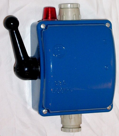 (click
it to view a large image)
(click
it to view a large image)
I got some Maxwell caps for free so I didn't have the chance of selecting any value, be it capacitance or voltage or anything else. Following the new trend, I'll build an MMC out of them - of course this will mean Multi Maxwell Cap here ;-) All Caps are 40kVpeak , I'll arrange them as follows: two 45nF in parallel for 90nF, and three 100nF in series/parallel for a total of 97.65nF@80kV (as you can see, the rotary spark gap SRSG will fit onto the same layer of my setup):
             o
             |
     +-------+
     |       |       S
     |100.2  |100.7  R
    === A   === B    S
     |       |       G
     |       |
     |       +-------+
     |       |       |
     |100.6  |45.58  |45.06
    === C   === D1  === D2
     |       |       |
     |       |       |
     +-------+-------+
             |
             o
| Double-ended, Plastic Case | 100nF-caps (A,B,C) | 45nF-caps (D1,D2) |
| Condition: | A: new B: used C: almost new |
D1: old, used D2: old. heavily used |
| Maxwell Model Number: | 31981 http://www.hvpower.com/plasticspecs.htm |
31677 |
| Serial Number: | A: 496564 B: 496563 C: 481217 |
D1: 275133 D2: 275134 |
| Capacitance Rating [nF]: | 100 | 45 |
| Voltage Rating [kV]: | 40 | 40 |
| Max Peak Current [kA]: | 25 | 25 |
| Max RMS Current [A]: | 25 | 24 |
| Design Life @ 20%VR @ rated voltage | 1x 10^8 cycles | 3x 10^7 cycles Max. voltage reversal: 25% |
| Operating Temp Range: | -10 to +40 °C | -30 to +65 °C |
| Approx. Inductance [nH]: | 60 | 50 (80) |
| Case Dimensions [mm^3]: (H x W x L) | 102 x 153 x 267 | 4.0 x 6.0 x 9.6" |
| Approx. Weight [kg]: | 5.5 | 4.2 |
I'll drive the 98nF-array with Urms=15kVac (Upeak=21.2kV) which will result in 22J per bang. At 200BPS, I'm going to pump about 4.4kW through them. With assumed losses of 20%, the input power will be about 5.3kVA (24A at 225V).
Have to calculate resocap-size (static gap: 160% of resocap size, SRSG: 320% of resocap size) for the Maxell-array described above.
According to John Freau's formula describing the spark length depending on
the wallplug power and the BPS:
spark length = 5.8 * sqrt (power input)
/ 4th root ( BPS),
I expect about 2.84m long sparks (just for comparison: with my 4"-TC I
got up to 1.43m long sparks (120cm typically) at <2.6kW
wallplug power and approx. 1100BPS. Johns formula predicts 1.3m here
which is very close to what I got).
My power supply for the BIGcoil are two potential xfmrs with 15kVrms, I plan to build a Synchronous Rotary Spark Gap (SRSG) with 200BPS. The frequency of my secondary including topload will be approx. 70kHz.
During a web search, I found two very useful charts about HV pluse discharge capacitor lifetime at Maxwells website. Maxwell is now part of General Atomics and due to this change, they reworked their website and removed the charts. So I decided to place this valuable information here:
I also found Jim Lux' page
<http://home.earthlink.net/~jimlux/hv/caplife.htm>
where the following formula is written (he states that it was from a paper,
some guys from Maxwell wrote):
Lx = Lref *
(Qref/Qx)^1.6 *
(Vref/Vx)^7.5
(please read the remark below, the 1.6 should better
be a 2.6 in my opinion!)
If both, the formula and the charts, are based on the
data found at Maxwell, the
data should match. I tried it and the voltage dependency
is really a perfect match:
But not so the voltage reversal data. Seems like the lifetime factor depends more on Qref/Qx raised to the 2.6th power than the 1.6th power. Perhaps a typo. Well, 2.8 will be a slightly better match though:
Jim wrote further: "...the life in a Tesla coil at 90% reversal (a Q of 15)..." and gives a useful formula for calculating the voltage reversal from the Q and vice versa. From these data it is obvious that the use of the caps in a TC will reduce their lifetime by a factor of 500 due to the high voltage reversal of 90% instead the rated 20%.
Decreasing the voltage increases the lifetime by the power of 7.5. So If I would only use one cap instead of two in series, it would last only 0.55% of the time it will now in my configuration.
My #31981 maxwell caps are rated for a lifetime of 10^8 cycles @ <20% voltage reversal @ rated voltage of 40kVpeak. From the formula above, the lifetime is decreased by a facor of 500 due to the voltage reversal, but increased by a factor of about 5400 due to the reduced voltage (15kVrms plus a saftey margin of 20% due to the safety gap setting). At 200BPS, this works out to about 1500h (=1e8/500*5500/200/3600). Some of the 15 years old caps obviously have been used in a strong way, lets assume there is only 10% of their lifetime left, so they will last 150h. Things get worse if one asume 95% voltage reversal instead of the 90% Jim suggested. In this case the lifetime will be reduced again by a factor of ten down to only 15h. Ok, these are very pessimistic assumptions but they still lead to 60 days of fun where I can run the coil for 30x half a minute! (A guy from a german distributor of Maxwell caps told me recently that Maxwell designs their Caps to 120% of the rated voltage and a 25% voltage reversal (instead of the rated 20%). So their lifetime should be (1.2^7.5)*(1/0.8) = 4.9 times higher than Maxwell tells us in the data sheets... This will lead to about 75hours of high voltage fun with my current configuration.)
(One thing to consider though: the MMC consists of many (n*m) caps, therefore the lifetime of the MMC (before the FIRST cap will fail) is approx. 1/(m*n) the liftetime of one cap alone.)
Then suddenly an idea came into my mind: there is a secondary coil in my setup! This means that
1) The ringing is not only damped (as Jim has said Q=15), but there is a sinusodial envelope because of the energy transfer between the primary and the secondary. So the effective amplitude of the voltage which stresses the cap is reduced. Good thing!
2) The spark gap quenches after the 3rd or the 5th notch, further reducing the effective amplitude of the voltage which stresses the cap. Again good thing!
Now on to the bad part:
3) When the energy is transferred back from the secondary into the primary, the voltage reversal is higher than 100%, perhaps even as high as 200% at the beginning! Bad bad thing....
At the time I realized this, I gave up - I didn't know the math to calculate the lifetime more accurately and I thought I'll ask you all what you think. PLEASE give me feedback if you have to say anything to this.
OK, now that I know that the voltage will not kill my caps instantanously,
I'll try to calculate the Irms. Terry's MMC program calculates 47.3Arms at
200BPS (57.9A at 300BPS). The caps are specified for 25Arms, so
everything should be ok (each string will see 24Arms), especially for short
time runs.
I have to look how Terry calculates the
Irms, meanwhile I'll try it myself:
If the Maxwell caps should ever fail, I still have the BIG cap (250nF/20kVDC), I can use with the pigs set to max. 7.5kV:
Driven with one pig (via "the anchor"), at 6.8kV and 200BPS, I
have a bang size of 11.6J and a wallplug power of approx.
2800W.
Driven with one pig (via "the anchor"), at 7.5kV and 200BPS, I have a
bang size of 14.1J and a wallplug power of approx 3400W.
Driven with two pigs (primary side in series), at 6.8kV and 300BPS, I
have a bang size of 11.6J and a wallplug power of approx.
4200W.
Archimedes flat spiral primary
static gap:
Up to 5kW (the max. value you'll get out of a single phase wallplug here
in Germany for short times) I'll try to use a static vacuum gap. It
will be 35mm dia Cu, zig-zag design with variable distance a la Scott R /
Jochen Kronjaeger for easy compensating the wear and eventually 'soft start'
for the coil by starting at some gaps closed by additional tubes which can
be removed remotely, adjustable air flow through the gaps (quenching fan)
+ high flow cooling fan). I'd like to build a "Scott D. / JK - gap"
(zickzack-design) out of 35mm dia copper tubes and want to modify the design
so that I'm able to use a vacuum motor (wow, a very strong one which I removed
from an old vacuum cleaner!) to suck air through the pipes for cooling purposes
and between the pipes to aid quenching (that will then be the
ScottD./JK/STK-gap!). I plan to make the gap adjustable by connecting more
ore less pipes in series (perhaps remotely on the fly via some air pressure
switches) or moving the two outer electrodes remotly nearer to or farther
away from the other electrodes. As the results of other coilers (like Finn)
shows, such a gap consisting of lots of small gaps (therefore the voltage
should be as high as possible) CAN be used up to 5kW, perhaps up to 7kW.
To much single gaps will result in more losses in the gap, so I will try
to use as few as possible. Therefore the gap width should be made variable
in a prototype I'll build.
rotary gap:
If the static gap will not quench good enough (I bet it will as I have seen
a standard muffin fan type RQ/RH cylindrical gap of a fellow coiler perform
very well with my pigs), I'll build an additional asynchronous rotary spark
gap (ASRSG) or even synchronous rotary spark gap (SRSG). A guy called David
wrote on 1st. of June 2000 on the TCML
("economical
rotary gap motor") that he acquired a bench grinder ("Black&Decker",
40$US) and modified it into a rotary gap. He reported that it functioned
very well. It cames that just at the day I've read this post in the TML achrive,
I found such a bench grinder (brand "parkside") in the supermarket below
my flat - and it costed me only 29.90DM which was about 15$US at this time!
More about my attempts in building an SRSG (including the photographs taken during this process) will be placed on its own page.
Data of the planned 10"-secondary (rough calculations):
| AntiRacingSparkRings
I plan to use them here in my BlueThunder project because I think I will try to max out this coil. As described in the section AntiRacingSparkRings of the secondary building page, it is better to use more rings wih smaller diameter on fat coils because they will get even more fatter due to the rings. To achieve a creepage path length of 1.5 times the winding length, one has to use 12 rings with an outer diameter of 12" for a 10" wide coil. |
| UPDATE 05'2002: at the hamfest in Neumarkt/Opf.
I found a big spool (4kg incl. wooden spool) of 0.7mm wire
=> its time to recalculate the design once again! (=> no
more wire needed!)
25cm = 10" Aussendurchmesser (mit bisher vorhandenem Draht): Gesamtlänge: 140cm angestrebte Funkenlaenge 3.5m, bei angestrebtem Faktor 2.5-3 also eine optimale Wicklungslaenge von 1.4-1.2m Rohr-Umfang: 0.79m mittl. Windungs-Umfang: 0.795m Wicklungslänge: 1:5 = 125cm (49") which will be enough for at least 8kW at 200BPS (or max. 5kW at 100BPS)
Platz unten:
Platz oben: 4cm für mechanischen Schutz der oberen Wicklung, ACR a la
Kurt aus Cu-Rohr mit passendem Steckkontakt zum Toroid
d 0.63mm 0.75 0.85
Faktor 0,1186 0,1104 0,1105 => +/- 4% Fehler
gesicherte Laengen: => nur bis auf 125cm wickeln (etwa 1570Wdg), dann bleibt etwas Draht übrig. FAZIT: Windungszahl 1570 ok, Gesamtlänge mit 140cm ok Spleissen mittels Anschraegen (bench grinder) und Loeten der Schraegen, dann Schlauch drueberziehen, Abstand zu benachbarten turns einhalten, gesondert vergießen.
Ctop = 30,7pF (6"-MDT mit ACR) ft = 66.5 kHz
Cpri = 97,5 nF (Maxwells)
Lpri => 59 uH für 66.5kHz! Lpri ~> 75 uH für 59kHz (großes 100cm x 12"-Toroid mit 45nF)! Lpri ~> 86 uH für 55kHz (ganz großes 120cm x 12"-Toroid mit 54nF)!
---------------------------------------------------- mögliche Toroide:
28" x 6,7" = 30,8nF |
I'll fix the 8"-secondary on the floor using metal angles. The angles will
be permanently screwed to the coil and detachable to the floor. Above the
angles I'll glue in the base plate into the coil to seal the inside airtight.
The angles will be connected electrically to the RF-gnd like the lower end
of the winding will.
         :- - - - - - - - - - -:       :
         :- - - - - - - - - - -:        \
         |---------------------|         > winding
         |---------------------|        /
         |---------------------|       '
         |_____________________|       ___ base plate (glued in)
        ||                     ||
      =8==O                   O==8=    --, srews
        ||                     ||       /
 _o_____||                     ||_____o_     angles
==|===================================|======== floor
|
With a size of the angles of 5cm, there will be 5 cm above them to the first turn. Therefore I'll have enough spacing to the primary (inner diameter 12").
![]()

![]()
![]()